

Direct vs Indirect Fire Suppression System: Which Configuration Fits Your Vehicle?
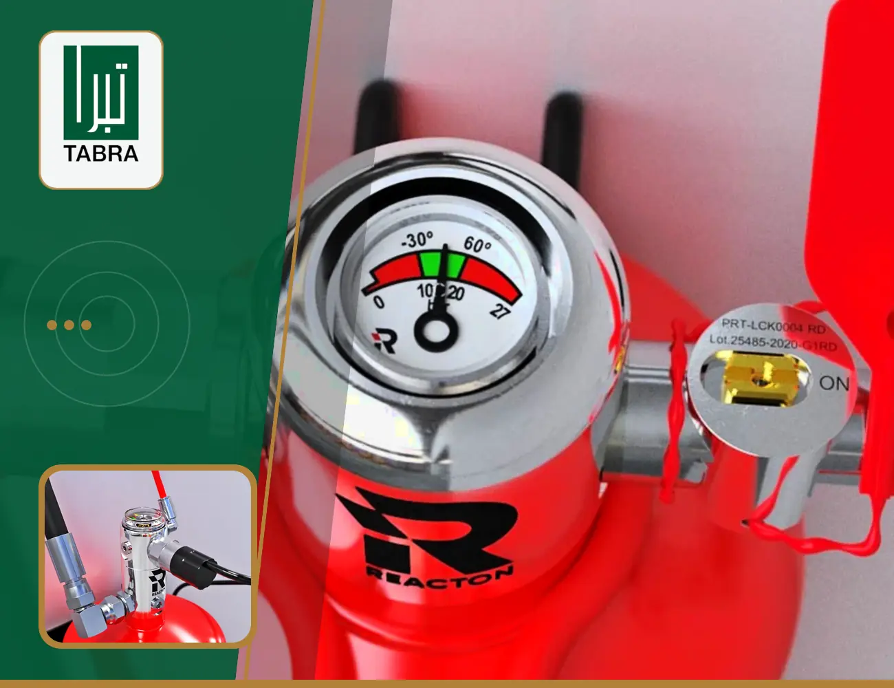
Choosing between a direct vs indirect fire suppression system is not simply a matter of selecting the smaller, cheaper or more familiar option. A direct-release system uses heat-sensitive detection tubing as both the detection mechanism and the discharge path. An indirect-release system uses detection tubing to activate a separate network that distributes the extinguishing agent through strategically positioned nozzles.
Neither configuration is automatically better. The correct choice depends on the vehicle’s fire hazards, compartment geometry, airflow, obstructions, operating conditions, extinguishing agent and applicable technical requirements.
This guide helps UAE fleet managers, procurement teams, transport operators and workshop managers evaluate those factors before requesting a technically meaningful quotation.
How Direct and Indirect Release Actually Differ
The clearest way to understand a direct vs indirect fire suppression system is to separate three functions:
- Fire or heat-condition detection.
- System activation.
- Extinguishing-agent discharge.
Both configurations may use heat- and flame-sensitive pneumatic detection tubing, but the route taken by the agent after activation is different.
Direct release: one tube performs two roles
In a direct-release configuration, the detection tubing is also used to discharge the extinguishing agent. When a section of tubing reaches its designed activation condition, it ruptures. The agent is then released through the opening created at or near the detected heat source.
This creates a close relationship between the point of detection and the point of discharge. It can be useful where the protected hazard is localized and the tubing can be routed appropriately around that hazard.
However, direct release should not be interpreted as “the agent always reaches the exact centre of the fire.” Its effectiveness still depends on:
- Tubing placement.
- The position of the developing fire.
- Physical barriers around the hazard.
- Air movement.
- The selected agent.
- The system’s approved design.
- Installation quality.
- Tube condition throughout its service life.
A direct system therefore requires more than attaching detection tubing somewhere inside a compartment.
Indirect release: detection and distribution are separate
In an indirect-release configuration, the detection tubing activates the system but does not act as the main discharge network. When the tubing activates, pressure loss operates a valve. The extinguishing agent then travels from the cylinder through separate hoses or pipework to one or more discharge nozzles.
This arrangement allows the discharge points to be selected separately from the detection route. That distinction can be valuable when a compartment contains several hazards, restricted access, substantial obstructions or areas requiring controlled agent distribution.
Indirect release does not automatically mean that the entire compartment is uniformly flooded. Actual coverage depends on the approved design, nozzle selection, nozzle orientation, agent quantity, discharge characteristics, compartment geometry and application.
Accordingly, neither architecture should be described using an absolute “targeted versus complete coverage” rule without examining the proposed system.
Direct vs Indirect Fire Suppression System Comparison
The table below highlights the architectural differences. It is a preliminary decision aid, not a substitute for an application-specific design.
| Assessment area | Direct release | Indirect release |
|---|---|---|
| Detection method | Heat-sensitive tubing detects the activation condition | Heat-sensitive tubing detects the activation condition |
| Discharge path | Agent releases through the activated section of tubing | Agent travels through separate pipework or hoses |
| Discharge point | Created at the tubing activation point | Predetermined by nozzle locations |
| Main design relationship | Detection route directly influences discharge location | Detection route and discharge points can be planned separately |
| Distribution flexibility | Depends heavily on tube routing and activation location | Nozzles allow planned distribution to defined locations |
| Components | May require fewer separate distribution components | Requires a separate discharge network and nozzles |
| Installation assessment | Must validate tube exposure and discharge suitability | Must validate both detection routing and nozzle coverage |
| Maintenance attention | Detection/discharge tube condition is critical | Detection tube, pipework and nozzle condition are all critical |
| Typical decision question | Can the tubing reliably detect and discharge at the relevant hazard? | Can dedicated nozzles provide the required distribution across the protected area? |
This direct vs indirect fire suppression system comparison should help teams ask better questions, but it cannot confirm vehicle compatibility by itself.
Start With the Hazard, Not the Product Name
A reliable selection process starts by identifying what can burn, where ignition may begin and how a developing fire could spread.
Relevant hazards may include:
- Fuel or oil lines.
- Hydraulic fluid.
- Electrical wiring and connections.
- Batteries and power-distribution components.
- Turbochargers.
- Exhaust components.
- High-temperature surfaces.
- Auxiliary equipment.
- Accumulated combustible contamination.
The importance of each hazard varies by vehicle. A bus engine compartment, refuse vehicle, excavator, mobile generator and heavy truck can have very different layouts and operating environments.
For each protected area, determine:
- The likely ignition points.
- The combustible materials present.
- Whether hazards are concentrated or distributed.
- What barriers could restrict detection or agent movement.
- Whether fire could develop behind shielding or inside a sub-compartment.
- Whether fans or vehicle movement create significant airflow.
- Which components move, vibrate or become extremely hot.
- What areas technicians must access during normal servicing.
The direct vs indirect fire suppression system decision should be made after this hazard map is developed—not before.
Use a Three-Layer Configuration Framework
Fleet teams can structure the assessment around three layers: hazard, geometry and environment.
Layer 1: Hazard characteristics
Ask what materials could contribute to the fire and what extinguishing performance is required. The release architecture alone does not determine whether the selected agent is appropriate.
Dry powder, wet chemical and clean-agent systems have different characteristics. Agent selection should account for the anticipated fire classes, system design, protected equipment, residue considerations and relevant technical requirements.
Do not assume that choosing DLP or ILP automatically determines the agent. The system manufacturer’s verified application guidance must govern the final combination.
Layer 2: Compartment geometry
Inspect the compartment rather than relying only on drawings. Look for:
- Shields and covers.
- Narrow passages.
- Multiple levels.
- Enclosed electrical boxes.
- Areas behind the engine.
- Compartments separated by panels.
- Service doors.
- Components that obstruct a potential discharge path.
- Available locations for the cylinder, tubing, pipework and nozzles.
A direct-release arrangement depends strongly on placing tubing where it can detect the relevant condition and discharge effectively. An indirect arrangement provides more freedom to place discharge nozzles, but those nozzles still require correct positioning and unobstructed distribution.
Layer 3: Operating environment
Vehicle systems face conditions that stationary cabinets may not experience:
- Continuous vibration.
- Road shock.
- Dust and contamination.
- High ambient temperatures.
- Water exposure.
- Repeated opening and closing of service panels.
- Airflow from fans.
- Repairs that change component positions.
- Abrasion from nearby wiring or metal edges.
When comparing a direct vs indirect fire suppression system, assess how these conditions affect every installed component over time, not merely how the system appears on the installation day.
Why “Small Compartment Means Direct” Is Not a Reliable Rule
Many simplified comparisons recommend direct release for small spaces and indirect release for larger ones. Size can influence the design, but it is not a complete selection rule.
A small compartment may contain several separated hazards that require planned nozzle distribution. A larger compartment may contain one clearly defined hazard around which detection tubing can be routed effectively. Conversely, either configuration may be unsuitable if the proposed agent, hardware or certified design does not cover that application.
The better questions are:
- Are the hazards localized or distributed?
- Can the detection route reach the important hazard areas?
- Could barriers prevent effective agent delivery?
- Is predetermined nozzle placement necessary?
- What airflow exists during normal operation?
- Does the proposed design match the manufacturer’s tested or certified configuration?
- Can the installation be inspected and maintained?
- What happens if technicians remove a panel or replace an engine component?
This approach turns the direct vs indirect fire suppression system choice into an engineering and risk decision rather than a rule-of-thumb purchase.
Vehicle Airflow Can Change the Decision
Airflow is particularly important in engine compartments. Cooling fans, ventilation openings and vehicle movement may affect heat development, detection conditions and agent distribution.
This does not mean one configuration always handles airflow better. It means the supplier should assess:
- Fan locations.
- Normal airflow direction.
- Changes in airflow at different engine speeds.
- Openings through which agent may escape.
- Obstructions that create sheltered zones.
- Whether shutdown or signalling functions form part of the proposed design.
- How nozzle orientation or tubing position accounts for the operating environment.
Ask the supplier to explain how the proposed system configuration addresses airflow. A generic diagram that ignores the actual vehicle is not enough evidence of compatibility.
Routing and Mechanical Protection Matter
Both DLP and ILP systems depend on components remaining secure and undamaged in a demanding environment.
Detection tubing should not be left vulnerable to:
- Sharp edges.
- Abrasive contact.
- Excessive bending.
- Unsupported movement.
- Unintended exposure to extreme heat.
- Interference from service tools.
- Contact with moving parts.
- Chemical contamination outside the material’s design limits.
Indirect systems add a distribution network that must also be correctly supported. Pipework, hoses and nozzles need protection from movement, impact and obstruction. Nozzle caps or protective features, where specified by the manufacturer, must remain in their intended condition.
These considerations may affect the direct vs indirect fire suppression system assessment because the most theoretically attractive discharge arrangement is not useful if it cannot be routed, supported, inspected and maintained safely.
Match the Configuration to Workshop Reality
A system must coexist with routine vehicle maintenance. Engine repairs, belt replacement, electrical work, battery servicing and cleaning can disturb fire-suppression components.
Before approving the installation design, involve workshop personnel and ask:
- Which panels are removed frequently?
- Which components require regular access?
- Could tubing be used incorrectly as a handhold?
- Could a mechanic accidentally block or redirect a nozzle?
- Will pressure or status indicators remain visible?
- Can the cylinder label and component identification be inspected?
- Does an engine replacement require redesign or reinspection?
- Who must be notified before welding or high-temperature work?
The operationally correct direct vs indirect fire suppression system is one that can maintain its designed configuration through the vehicle’s real maintenance cycle.
A UAE-Specific Regulatory Check
The UAE has a technical-regulation framework for fire-suppression systems intended for the engine compartments of buses and coaches. UAE Cabinet Resolution No. 20 of 2021 identifies UAE.S 5041:2021 within that framework.
Fleet operators should avoid extending this statement to every commercial vehicle or every suppression application. Requirements can depend on the vehicle category, passenger capacity, application, emirate-level process, tender specification and responsible authority.
The release architecture alone does not establish compliance. A DLP or ILP description does not prove that:
- The exact product has applicable conformity.
- The selected agent and cylinder are within scope.
- The proposed configuration matches the tested arrangement.
- The installer has the required status.
- The vehicle-specific installation is acceptable.
- A certificate will be issued.
- An inspection will be passed.
Current product-conformity information can be checked through the UAE Ministry of Industry and Advanced Technology. Verification should use the exact manufacturer, system, model and certificate scope.
For vehicles outside the defined bus and coach scope, operators should confirm the requirements applicable to their vehicle, contract and operating authority rather than assume the same rule applies.
Separate Six Types of Evidence
Procurement teams should distinguish between six records that are often incorrectly grouped under the word “approval.”
1. Product conformity
Evidence that a defined product or system falls within the scope of a particular conformity assessment. It does not automatically cover every model, agent or application sold by the manufacturer.
2. Manufacturer certification
Evidence that a manufacturer or product has been assessed against a particular standard. The certificate’s model references, configuration, agent and application scope matter.
3. Installer authorization or competence
Evidence concerning the organization or personnel performing the installation. This is separate from product certification.
4. Vehicle-specific installation record
Documentation of what was installed on a particular vehicle, including the system identification and protected application.
5. Inspection or test result
A record of a defined check performed at a stated time. It should not be presented as permanent proof that the system will remain acceptable after modification or damage.
6. Certificate issuance
A document issued under a particular process and scope. Its presence should not be confused with universal product or installer approval.
Before choosing a direct vs indirect fire suppression system, request documentary evidence that applies to the exact proposed configuration.
Pre-Purchase Compatibility Checklist
Provide the supplier with enough information to perform a meaningful technical review.
Vehicle identification
- Vehicle registration card.
- VIN or chassis number.
- Make and model.
- Model year.
- Vehicle category.
- Passenger capacity where relevant.
- Engine make and model, if available.
Application information
- Engine or equipment location.
- Areas requiring protection.
- Existing suppression equipment.
- Previous system documentation.
- Major vehicle modifications.
- Auxiliary equipment.
- Fleet or tender requirements.
Visual and operational information
- Clear compartment photographs.
- Photographs with service panels open.
- Approximate dimensions where requested.
- Typical operating environment.
- Duty cycle.
- Exposure to dust, heat, water or corrosive conditions.
- Maintenance practices.
- Known vehicle variants within the fleet.
A quotation issued without adequate technical information may not establish whether the proposed direct vs indirect fire suppression system fits the actual vehicle.
Questions to Ask the Supplier
Before approving a system, ask:
- Which release configuration is proposed, and why?
- Which hazards and areas are included in the protected scope?
- How are detection tubing and discharge points positioned?
- What extinguishing agent is proposed?
- How does the design account for airflow and obstruction?
- Which exact manufacturer documents support this application?
- What conformity or certification evidence applies to the proposed model?
- Does that evidence cover the agent, cylinder and configuration offered?
- What vehicle-specific installation documents will be provided?
- What inspections and maintenance are required by the manufacturer?
- What must happen after discharge, pressure loss or component damage?
- Which engine repairs or vehicle modifications require system review?
- How will different models or model years be managed during a fleet rollout?
- Can a representative vehicle be assessed before standardizing the design?
The quality of the answers will usually provide more decision value than a generic claim that one architecture is superior.
Plan a Fleet Rollout by Vehicle Family
Do not assume that one installation design fits every asset recorded under the same fleet category.
Group vehicles by:
- Manufacturer.
- Model.
- Model year or generation.
- Engine configuration.
- Compartment layout.
- Fuel or power type.
- Installed auxiliary equipment.
- Duty cycle.
- Operating environment.
Begin with a representative vehicle from each group. Document layout differences and confirm whether the proposed configuration needs adjustment.
This process is especially important when the direct vs indirect fire suppression system decision depends on tubing routes, nozzle positions, compartment barriers or available mounting points.
A controlled rollout can also help the fleet establish:
- Standard vehicle-data forms.
- Installation records.
- Component-identification methods.
- Inspection checklists.
- Workshop notification procedures.
- Maintenance schedules.
- Reassessment triggers.
Post-Installation Verification Checklist
After installation, confirm that the supplied documentation and visible installation correspond.
Check:
- System and cylinder identification.
- Protected area stated on the installation record.
- Secure cylinder mounting.
- Detection tubing condition and support.
- Separation from sharp edges and moving components.
- Distribution pipework and hoses where applicable.
- Nozzle quantity, location and orientation where applicable.
- Pressure or system-status indication.
- Manual activation and signalling components where specified.
- Labels and instructions.
- Inspection and maintenance information.
- Actions required after discharge or system damage.
Fleet administrators should also record the vehicle number, VIN, installation date, system identification and next required service action in the asset-management system.
This is not a substitute for a technical inspection. It is an administrative check that helps prevent missing records and undocumented vehicle changes.
Mistakes That Can Undermine Either Configuration
Selecting from a generic product photograph
A photograph cannot establish hazard coverage, component routing or vehicle compatibility.
Choosing architecture before choosing the protected scope
The team must first define which compartment and hazards require protection.
Treating agent selection as a secondary detail
The agent is a fundamental part of the suppression design and must suit the hazard and verified system configuration.
Assuming every certificate covers every model
Certification scope can be limited. Review exact model references and conditions.
Ignoring later vehicle modifications
Moving a battery, installing auxiliary equipment or changing engine components can alter the protected environment.
Blocking nozzles during maintenance
In an indirect system, a nozzle that is obstructed, redirected or contaminated may no longer provide the intended distribution.
Damaging detection tubing
Because tubing performs a detection function in both architectures—and a discharge function in a direct system—damage requires competent assessment rather than an improvised repair.
Purchasing for the entire fleet before checking variants
A single fleet can contain materially different engine compartments even when vehicles perform the same operational role.
Avoiding these mistakes is as important as the original direct vs indirect fire suppression system selection.
How Tabra Can Support the Configuration Review
Tabra General Trading LLC has operated in the UAE since 1997 and offers REACTON automatic fire-suppression solutions from its Dubai and Abu Dhabi locations.
A useful initial enquiry should include:
- Registration card.
- VIN.
- Make, model and model year.
- Vehicle category.
- Engine-compartment photographs.
- Number of vehicles.
- Existing system or certificate details.
- Relevant tender, fleet or authority requirements.
Tabra can then review the information and discuss the proposed application. A technical review should come before claims about compatibility, conformity, inspection acceptance, installation timing or price.
For product information, see:
- REACTON Automatic Fire Suppression Systems
- REACTON Direct Release Systems
- REACTON In-Direct Release Systems
Is direct release always better for a small vehicle compartment?
No. Compartment size is only one factor. Hazard locations, barriers, airflow, tubing routes, extinguishing agent and conformity scope must also be considered. A small compartment with several separated hazards may still require a different distribution strategy.
Does an indirect system detect fire through its nozzles?
Not necessarily. In the REACTON ILP architecture described by the manufacturer, heat-sensitive detection tubing detects the condition and activates the valve. The suppression agent then travels through a separate discharge network to the nozzles.
Can a direct system protect an engine compartment?
Potentially, but suitability must be confirmed for the particular system, vehicle, hazard and applicable requirements. The word “direct” alone does not establish appropriate coverage or conformity.
Which is easier to maintain: DLP or ILP?
Maintenance requirements depend on the exact product and manufacturer guidance. DLP places particular importance on the condition of tubing that performs detection and discharge. ILP requires attention to detection tubing as well as the separate pipework, hoses and nozzles.
Is the extinguishing agent determined by the release type?
No. Release architecture and agent selection are related but separate decisions. The agent must be suitable for the anticipated fire hazards and supported by the verified system design.
How should I compare a direct vs indirect fire suppression system for a mixed fleet?
Group vehicles by make, model, year, engine layout and operating environment. Assess a representative asset from each group, then confirm whether the same system design and documentation apply across all variants.
Does UAE.S 5041:2021 apply to every commercial vehicle?
It should not be described as a universal requirement for every commercial vehicle. The relevant UAE technical-regulation framework concerns fire-suppression systems intended for engine compartments of buses and coaches. Operators should verify the exact scope and any other applicable requirements.
What should I send before requesting a quotation?
Send the registration card, VIN, make, model, model year, vehicle category, clear compartment photographs, fleet quantity and any existing suppression-system or tender documentation. This supports a more meaningful technical review.
Conclusion: Select the Configuration Through Evidence
The right direct vs indirect fire suppression system cannot be selected reliably from vehicle size, price or a generic list of benefits.
Start with the hazards. Examine the compartment geometry and operating environment. Confirm the detection and discharge paths. Evaluate the agent separately. Check the exact scope of conformity and manufacturer documentation. Finally, make sure the installation can remain inspectable and maintainable throughout the vehicle’s service life.
To discuss a vehicle or multi-vehicle application with Tabra, provide the vehicle registration card, VIN, make, model, model year and clear photographs of the area requiring protection. Tabra can use that information as the starting point for a compatibility and configuration review—without promising universal compatibility or inspection acceptance before the technical assessment is complete.